Ashish Alfred
Modeling of Hexapod with Robotic Arm
Objective
This team-driven project is intended to integrate and apply the knowledge I have gained in learning computer-aided design and computer-aided engineering. In a team of four, I am required to design, perform meshing and analyze each component that can solve real-world challenges.
We have decided to design a robot that has the ability to manipulate and locomote at the same time. So as to come up with the solution, we have combined two robots together, first is Hexapod, which has the ability to locomote that is to move from one place to another, its best feature is that it can walk on rough terrain and has the ability to stay stable and keep on walking if one or more legs are disengaged. The second robot is the Robotic Arm which has the ability to manipulate objects that is pick or drop objects, and its best feature is to mimic the human arm.
The motivation for this project is based on the fact that during treasure hunting operations, we humans are likely to destroy objects, and it can help soldiers by diffusing land mines from a safe distance.
Implementation
Motivation
-
Ability to work on Rough Terrain
-
Speed of operation using better Gait
-
Ability to locomote and manipulate
-
Large workspace of Robotic Arm
Methodology

Stage One
Designing of the hexapod and performing FEA analysis on each component of Hexapod. And on the basis of analysis results selecting the optimum design.
1. Chassis of hexapod - It is that part of hexapod that holds microprocessor, sensors, battery, etc. And the leg of the hexapod and robotic arm are attached through it.

Rectangular Chassis
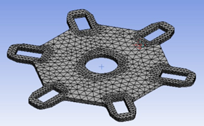
Circular Chassis

Total Deformation analysis of rectangular chassis

Total Deformation analysis of circular chassis
Boundary Condition for chassis - 3 servo slots are kept fixed because during stance phase 3 legs will provide support to the chassis and force of 30N is applied at the middle.
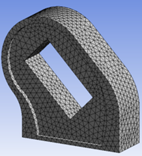
2. Femur - It connects the leg of hexapod with the chassis and help the leg to take next position by moving forward or backward.

Femur 1

Femur 2

Total Deformation analysis of Femur 1

Total Deformation analysis of Femur 2
Boundary Condition of total deformation of femur - One side of the femur is fixed and on the other side a force of 30N is applied making it a cantilever beam.
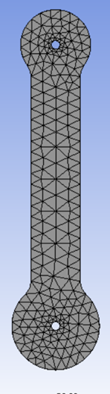
3. Tibia - It is also called leg or end effector of the hexapod all the load of electric components, chassis, and a robotic arm will be bared by the tibia.

Tibia 1

Total Deformation analysis of Tibia 1


Tibia 3
Tibia 2

Total Deformation analysis of Tibia 2

Total Deformation analysis of Tibia 3
Boundary Condition of total deformation of Tibia - In this servo slots are fixed and a normal reaction force of 40N is applied at the tip.
4. Final Leg assembly -

Rendered image of leg assembly
Stage Two
Designing of the Robotic Arm and performing FEA analysis on each component of Rbobotic Arm. And on the basis of analysis results selecting the optimum design.
1. Base of Robotic Arm -
Robotic arm base

Total Deformation analysis of robotic arm base
2. Upper Arm-
Upper arm

Total Deformation analysis of Upper arm
3. Robotic Arm Elbow-

Elbow

Total Deformation analysis of Elbow
4. Robotic Arm Forearm-

Forearm

Total Deformation analysis of Forearm
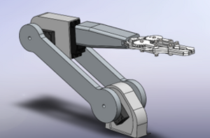
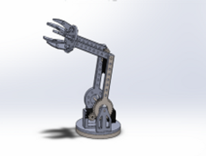
5. Final Robotic Arm Assembly -

Rendered image of Robotic Arm
Design Concept
Morph Chart for Hexapod


Model 1
Model 2
Model 3

Morph Chart for Robotic Arm

Model 1
Model 2
Model 3

Result
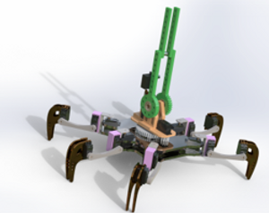
Successfully designed, analyzed, and assembled the Hexapod with Robotic Arm with the help of Solidworks and Ansys software. And was able to keep the robot weight under 2 Kg and payload capacity of 1.5 Kg.
For this project, we scored A+.

Rendered Image of Hexapod with Robotic Arm